Instructor <a href="instructor-velimir">Velimir</a> in Electrical Engineering
- 3T - Basic Reliability Analysis of Electrical Power Systems$50.00Learn More
Description:
This course discusses various power cable testing procedures including visualinspection, cable failures and their analysis, insulation and conductor defects, fieldtesting of medium voltage cables and different cable testing methods.This course is suitable for electrical engineers with a desire to understand thefundamentals of power cable testing. Course covers issues related to different failuretypes such as mechanical failures, overheating, chemical actions etc. and ways tomitigate them and to put cables back into the service. Upon successful completionengineers will be able to address various cable testing terms and procedures, tounderstand effects of such failures and how to organize mitigation measures in atimely manner so the service interruption time is minimized. - 5T-Harmonic Analysis Basics$75.00Learn More
Description:
This course discusses various power cable testing procedures including visualinspection, cable failures and their analysis, insulation and conductor defects, fieldtesting of medium voltage cables and different cable testing methods.This course is suitable for electrical engineers with a desire to understand thefundamentals of power cable testing. Course covers issues related to different failuretypes such as mechanical failures, overheating, chemical actions etc. and ways tomitigate them and to put cables back into the service. Upon successful completionengineers will be able to address various cable testing terms and procedures, tounderstand effects of such failures and how to organize mitigation measures in atimely manner so the service interruption time is minimized. - 6T-Arc Flash Calculation Methods$90.00Learn More
This course gives an overview of arc flash hazard computations suggested by IEEE and NFPA. All formulas and calculation procedures presented in this course are the property of the IEEE and NFPA. Students are encouraged to consult the standards for additional details.
This course is suitable for engineers with a desire to understand procedures for completing arc flash studies. Course covers arc flash calculation methods, approach boundaries, incident energy, calculation of the arcing time, determining risk category, information presented on single line diagrams, reports and labels.
Learning Objectives
This continuing education course is intended to provide you with the following specific knowledge and skills:
Arch flash calculation methods
Approach boundaries
Incident energy
Calculation of arcing time
Determining risk category
Assessment results format used on single line diagrams, reports and labels
- 4T- Limiting Arc Flash Exposure$60.00Learn More
Arc flash incidents may happen despite care taken to avert them. In such circumstances, it is always better if the incident energy is low and staff is ready for the worst by implementing adequate PPE. Arc flash incidents can be cut down by use of adequate equipment, proper preventive care, planning and coordination of operation, as well as skill improvement and real experience. Also crucial is the mental and physical circumstances of the staff such that the dropping of equipment and tools, accidental touching, etc., are averted.
This course is suitable for engineers with a desire to understand the how to limit arc flash exposure. Course covers discussion on preventive operation, limiting fault currents and adjustments of protection settings and personal protective equipment.
Learning Objectives
This continuing education course is intended to provide you with the following specific knowledge and skills:
Limiting arc flash exposure
System preventive operation
Limiting short circuit currents and arcing times
Adjustment of protective settings
Personal protective equipment selection
- 5T-Power Quality Measurements - Essential Theory$75.00Learn More
The decline in quality of power is a big issue due to increase in the usage of power electronics that uses inverters, an increase of unbalanced loads like large furnaces or rectifiers, and typically complex power distribution due to an increment in power network interconnections for new energy plants, etc. Inadequate power quality induces potential problems in receptacle/transmission devices and electronic apparatus malfunctions.
Power supply network issues that are induced by inadequate power quality are a frequent issue for both electric power providers and consumers. Nevertheless, it is not simple to tell if the source of inadequate power supply quality is at the provider’s side or the consumer’s system. Depending on this arrangement, power quality measurement is required to know the actual source of power quality issues as well as to treat and assess for efficient countermeasures.
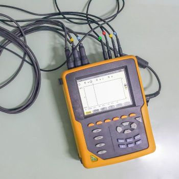
This course is suitable for engineers with a desire to basic theory necessary for power quality measurements. Presented details cover issues related to power quality events and parameters, sampling techniques, basic principles of measuring devices, statistical techniques used for processing results, connection of measuring instruments and their features. Practical steps for measuring process are also mentioned.
Learning Objectives
This continuing education course is intended to provide you with the following specific knowledge and skills:
Description of power quality events and parameters
Sampling techniques
Measuring device basic operating principles
Statistical techniques used for result processing
Connection of measuring instruments and their characteristics
Practical measuring steps
- 6T-Switching Transients Analysis Fundamentals$90.00Learn More
Switching transients severe enough to cause problems in industrial power systems are most often associated with inadequate or malfunctioning breakers or switches and the switching of capacitor banks and other frequently switched loads. The arc furnace system is most frequently studied because of its high frequency of switching and the related use of capacitor banks.
By properly using digital computer programs these problems can be detected early in the design stage. In addition to these types of switching transient problems, digital computer programs can be used to analyse other system anomalies such as lightning arrester operation.
This course begins with a discussion of the switching transient phenomena, describes root causes and explains system operation is affected. A detailed explanation of modelling and calculation procedure is offered. Selection and sizing of surge arrester is covered in details. Explained techniques can be implemented in any commercial power system software package.
Specific Knowledge or Skill Obtained
This course teaches the following specific knowledge and skills:- Power system switching studies fundamentals
- Typical circuit parameters for transient studies
- System modelling
- 8T-High Voltage Busbar Protection$120.00Learn More
Course Highlights
The protection arrangement for an electrical system should cover the whole system against all possible faults. Line protection concepts, such as overcurrent and distance arrangements, satisfy this requirement, even though short circuits in the busbar zone are cleared after certain time delay. But in the case, unit protection is used for feeders and plants, the busbars are not inherently protected.
It is a fact that the risk of a short circuit happening on modern metal clad equipment is insignificant, but it cannot be completely dismissed. Nevertheless, the damage resulting from one short circuit may be huge, up to the overall loss of the substation by fire. Severe damage or destruction would possibly end in widespread and prolonged supply disruption.
This course is suitable for electrical engineers with a desire to understand the fundamentals of high voltage busbar protection. Presented details cover key technical concepts, design arrangements and protection types. Upon successful completion engineers will be able to address the most important high voltage busbar protection arrangements and principles and appropriate application.
Learning Objectives
This continuing education course is intended to provide you with the following specific knowledge and skills:
System protection schemes including frame-earth protection
Differential protection principles
High impedance differential protection
Low impedance differential protection
Arrangement of CT connections
Interlocked overcurrent busbar schemes
- 10T- Protection Relay Testing and Commissioning$150.00Learn More
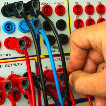
Protection Relay Testing and Commissioning Course Highlights
The testing and verification of protection devices and arrangements introduces a number of issues. This happens because the main function of protection devices is related to operation under fault conditions so these devices cannot be tested under normal operating conditions. This problem is worsened by the growing complexity of protection arrangements, application of protection relays with extensive software functionalities, and frequently used Ethernet peer-to-peer logic.
The testing and verification of relay protection devices can be divided into four groups:
Routine factory production tests
Type tests
Commissioning tests
Occasional maintenance tests
This course is suitable for electrical engineers with a desire to understand the fundamentals of protection relay testing and commissioning. Presented details cover basic testing terminology, various tests including factory production, type tests, commissioning and maintenance tests. Upon successful completion engineers will be able to address different tests, related procedures, outcomes, simulation hardware and software and procedures during protection relay commissioning and occasional maintenance. - 8T- Practical Power Cable Ampacity Analysis$120.00Learn More
Practical Power Cable Ampacity Analysis
In Practical Power Cable Ampacity Analysis, you'll learn...- -Basic theory and factors that stand behind underground cable ampacity calculations
- -How underground cable installation methods affect cable current carrying capacity
- -Numerical methods that are used underground cable sizing including voltage drop and short circuit current calculations
- -How to calculate underground cable current carrying ampacity following real world examples
Overview
Cable ampacity studies calculate the current-carrying capacity (ampacity) of power cables in underground or above ground installations. This ampacity is determined by the maximum allowable conductor temperature. In turn, this temperature is dependent on the losses in the cable, both I2R and dielectric, and thermal coupling between heat-producing components and ambient temperature.
The ampacity calculations are extremely complex. This is due to many considerations, some examples of which are heat transfer through the cable insulation and sheath, and, in the case of underground installations, heat transfer to duct or soil as well as from duct bank to soil. Other considerations include the effects of losses caused by proximity and skin effects. In addition, depending on the installation, the cable-shielding system may introduce additional losses. The analysis involves the application of thermal equivalents of Ohm’s and Kirchoff’s laws to a thermal circuit. - 6T- Introduction to Protective Device Coordination Analysis$90.00Learn More
Practical Power Cable Ampacity Analysis
In Practical Power Cable Ampacity Analysis, you'll learn...
- -Basic theory and factors that stand behind underground cable ampacity calculations
- -How underground cable installation methods affect cable current carrying capacity
- -Numerical methods that are used underground cable sizing including voltage drop and short circuit current calculations
- -How to calculate underground cable current carrying ampacity following real world examples
OverviewCable ampacity studies calculate the current-carrying capacity (ampacity) of power cables in underground or above ground installations. This ampacity is determined by the maximum allowable conductor temperature. In turn, this temperature is dependent on the losses in the cable, both I2R and dielectric, and thermal coupling between heat-producing components and ambient temperature. The ampacity calculations are extremely complex. This is due to many considerations, some examples of which are heat transfer through the cable insulation and sheath, and, in the case of underground installations, heat transfer to duct or soil as well as from duct bank to soil. Other considerations include the effects of losses caused by proximity and skin effects. In addition, depending on the installation, the cable-shielding system may introduce additional losses. The analysis involves the application of thermal equivalents of Ohm’s and Kirchoff’s laws to a thermal circuit.






Validate your login
Registrarse
Crear una nueva cuenta